A practical guide for structural engineers transitioning from steel to glass-fibre-reinforced polymer (GFRP) reinforcement, aligned with ACI CODE-440.11-22.
The mental model you have to unlearn
Almost every structural engineer was trained on a single, deeply ingrained design instinct: size the section for strength, then check serviceability as an afterthought. For steel-reinforced concrete that instinct is usually correct. Steel yields, the section warns you before it fails, and once you have satisfied the ultimate limit state (ULS) the deflection and crack-width checks are typically a formality.
With glass-fibre-reinforced polymer (GFRP) bars, that instinct quietly leads you astray. GFRP-reinforced flexural members are, in the overwhelming majority of practical cases, governed by serviceability, not by ultimate strength. Deflection, crack width and a third constraint that has no equivalent in steel design — creep rupture under sustained load — usually decide the section long before the bending capacity does.
This is not a minor numerical adjustment. It is an inversion of the design hierarchy, and it flows directly from two material facts: GFRP has no yield point, and it has a modulus of elasticity roughly a quarter that of steel. Understanding why serviceability governs — and how to design around it efficiently — is the single most valuable thing an engineer can learn before specifying composite reinforcement. This article walks through the mechanics, the code provisions in ACI CODE-440.11-22, and a practical workflow that turns the “problem” of low stiffness into a controlled, economical design.
The material behaves nothing like steel
To design with GFRP you have to take its constitutive behaviour seriously rather than treating it as “steel that doesn’t rust.”
It is linear-elastic to rupture, with no yield plateau. A GFRP bar loaded in tension follows an essentially straight stress–strain line all the way to failure, then ruptures suddenly. There is no plastic region, no fluid transition, no visible warning analogous to a yielding steel bar. Failure of the bar itself is brittle and abrupt. This is the defining characteristic that reshapes everything downstream.
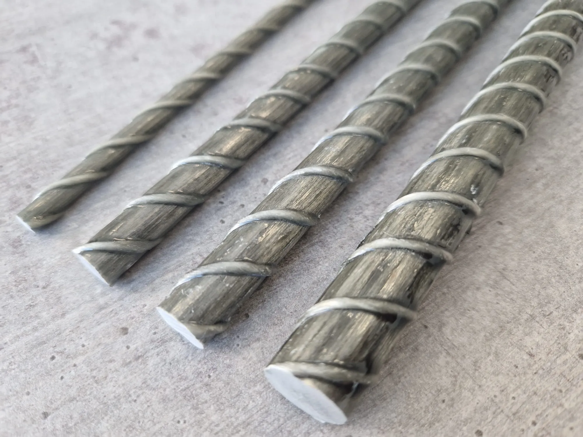
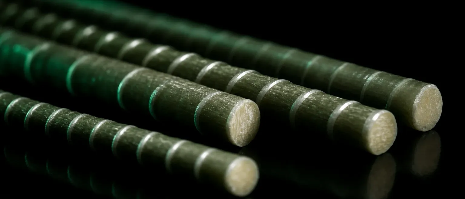
It is strong but not stiff. Typical commercial GFRP bars develop guaranteed tensile strengths in the range of roughly 600–1,200 MPa — frequently higher than the nominal yield strength of conventional reinforcing steel. But the modulus of elasticity tells the opposite story. ASTM D7957 sets a minimum tensile modulus of about 44.8 GPa (6,500 ksi); commercial bars typically fall between roughly 50 and 65 GPa. Compare that with steel’s ≈ 200 GPa and the picture is stark: GFRP is only about a quarter to a third as stiff as steel. High strength, low stiffness — that combination is the engine behind everything that follows.
It is anisotropic. The fibres carry load efficiently along their axis and very little across it. Transverse strength, shear/dowel resistance and the strength of the bar where it is bent are all substantially lower than the straight longitudinal tensile strength. A bent portion of a GFRP bar may retain only a fraction of the strength of the straight bar, which has direct consequences for stirrups, hooks and development.
It is light. At roughly a quarter of the density of steel, GFRP changes site logistics — but that is a handling advantage, not a design driver, and it is not the subject of this article.
Two of these facts — no yield, low modulus — combine to flip the design hierarchy. Let us take them in order.
Consequence 1: the failure-mode hierarchy is inverted
In steel design, the preferred failure mode is tension-controlled: the steel yields well before the concrete crushes, the member deflects visibly, cracks open, and the structure telegraphs distress long before collapse. ACI 318 rewards this ductile behaviour with a generous strength-reduction factor (φ = 0.90 for tension-controlled sections) and penalises brittle compression-controlled behaviour (φ = 0.65).
GFRP has no yield, so a “tension-controlled” GFRP section — one that fails by rupture of the bar — fails suddenly and catastrophically, with little warning. That is precisely the mode you want to avoid. The less-bad alternative is concrete crushing (compression-controlled), because crushing concrete at least produces some visible distress and a more gradual loss of capacity than an exploding bar.
ACI CODE-440.11-22 therefore deliberately encourages over-reinforced sections in which concrete crushing governs. The reinforcement ratio is pushed above the balanced ratio ρ_fb (the ratio at which bar rupture and concrete crushing would theoretically occur simultaneously), so that the concrete reaches its crushing strain of 0.003 first. The strength-reduction factors follow this logic and, relative to steel, appear inverted:
- φ = 0.55 for tension-controlled sections (GFRP bar rupture — the brittle, undesirable mode)
- φ = 0.65 for compression-controlled sections (concrete crushing — the preferred mode), with a transition region between the two.
So the same underlying philosophy as steel — reward the less brittle failure mode — produces numbers that look upside down to a steel designer. The headline consequence is this: GFRP flexural members are intentionally designed as over-reinforced, and they carry comparatively low φ factors. Both effects mean you put a generous quantity of bar into the section, which means the bending capacity is rarely the thing you are short of. The strength is, in a sense, abundant. What you run out of is stiffness.
Consequence 2: why ultimate strength almost never governs
Because designers provide an over-reinforced section with high-strength bar, the nominal moment capacity φM_n typically sits comfortably above the factored demand M_u. Worked examples in the literature routinely show φM_n exceeding M_u by large margins once the section has been sized to satisfy other checks. The bending strength is along for the ride.
The binding constraints are the serviceability limit states (SLS) and the durability-related sustained-stress limit. There are three of them, and any one can govern:
- Deflection under service load
- Crack width (or, in code form, bar spacing) under service load
- Creep-rupture stress under the sustained portion of the service load
Let us look at each, because each behaves differently from its steel counterpart.
Serviceability state 1: deflection
This is usually the headline. Low modulus translates almost directly into large deflection, through two compounding mechanisms.
The cracked section is far less stiff. After cracking, the flexural stiffness of a reinforced concrete section depends on the cracked moment of inertia I_cr, which is a function of the modular ratio n_f = E_f / E_c. For GFRP, n_f is only about a third to a half of the steel value. A smaller modular ratio raises the neutral axis and shrinks the cracked transformed section, so I_cr for a GFRP section can be a small fraction of the equivalent steel section’s. Less I_cr means more curvature for the same moment, and more curvature integrates into more deflection.
The effective stiffness has to be computed differently. For decades, engineers used Branson’s empirical equation for the effective moment of inertia I_e. Branson’s formula was calibrated for the relatively heavily reinforced, stiff sections typical of steel design, and it badly over-predicts the post-cracking stiffness — and therefore under-predicts deflection — for the lightly reinforced, low-stiffness sections typical of FRP. Using Branson on a GFRP slab can under-predict deflection by 30–40 %, which is exactly the wrong direction for a serviceability check.
ACI 440 (and now ACI CODE-440.11-22) addresses this by adopting the approach proposed by Bischoff, which is built on a weighted average of member flexibility rather than stiffness and is far more accurate for cracked FRP members. The formulation introduces an integration factor γ that accounts for the variation of stiffness along the span and depends on the load pattern and boundary conditions; for a simply supported member under uniformly distributed load, ACI recommends:
γ = 1.72 − 0.72 (M_cr / M_a)
with weighted combinations of positive- and negative-region values used for continuous spans. The key engineering point is not the exact algebra but the takeaway: use the Bischoff-based I_e from the code, not a Branson value carried over from steel habits, or you will under-design the depth.
The bottom line. For a given geometry and load, a GFRP-reinforced member will deflect roughly two to four times as much as the equivalent steel-reinforced member. The deflection limits themselves (L/240, L/480, etc.) are unchanged from ACI 318 — the structure still has to stay within them — so the engineer has to find that stiffness somewhere.
Where to find it. Deflection is dominated by section depth, because flexural stiffness scales with depth cubed. Increasing effective depth d is by far the most powerful and most economical lever: a modest increase in slab or beam depth buys a disproportionate reduction in deflection. Secondary levers include increasing the reinforcement ratio (more bar raises I_cr and lowers service-load stress), specifying a higher concrete strength (which raises both E_c and the cracking moment M_cr, delaying and reducing cracking), and using flanged or T-sections to add compression-zone stiffness. The practical design rule is simple: start from a deeper section than steel intuition suggests, and let depth — not bar quantity — be your primary deflection control. Where headroom or architectural depth is tightly restricted, that is precisely the project type where GFRP deflection will fight you hardest, and it should be flagged early.
Serviceability state 2: crack width — and why the rules are more relaxed
Here the inversion runs in the engineer’s favour, and it is one of the most misunderstood aspects of GFRP design.
In steel-reinforced concrete, crack-width control exists primarily to protect the steel from corrosion. Cracks let in moisture, chlorides and oxygen; limiting crack width (commonly to around 0.3–0.4 mm) slows the ingress that drives reinforcement corrosion. The entire apparatus of bar-spacing limits in ACI 318 is, at root, a corrosion-durability provision.
GFRP does not corrode. The chief reason to keep cracks narrow has therefore evaporated. What remains are secondary concerns — aesthetics, watertightness where required, and, in some climates, the risk that very wide cracks promote freeze-thaw deterioration of the concrete itself. Because of this, the codes permit wider cracks in GFRP-reinforced members than in steel. ACI 440.1R-15 allowed crack widths on the order of 0.5 mm (interior) up to roughly 0.7 mm (exterior), and the bar-spacing provisions in ACI CODE-440.11-22 are calibrated to a crack width of about 0.71 mm (0.028 in.) — explicitly tied to durability of the concrete against freeze-thaw rather than to protection of the reinforcement.
A few practical notes flow from this:
- Crack width is governed in code form through maximum bar spacing. You satisfy it by detailing, not by an explicit width calculation in most routine work.
- Bond surface matters. The crack-width behaviour of GFRP depends strongly on the bar’s bond characteristics, captured by a bond coefficient k_b. Different surface treatments — sand-coating versus helically grooved or ribbed surfaces — produce different k_b values and therefore different crack patterns; specifying the right surface enhancement is a genuine design choice, not a cosmetic one.
- The cracks are wider but more benign. Larger cracks mean reduced aggregate interlock, which feeds back into the shear discussion below — but they do not threaten the reinforcement, which is the whole point of using GFRP in aggressive environments.
In short: crack-width control is relaxed, not abandoned, and it rarely governs by itself. But the reason it is relaxed is the corrosion immunity that justifies the whole material choice, so it is worth explaining clearly to clients and checking authorities who may instinctively apply steel crack limits.
Serviceability state 3: creep rupture — the constraint with no steel equivalent
This is the check that catches engineers off guard, because nothing in steel design prepares them for it.
Glass fibres held under sustained tensile stress in a moist, alkaline environment are susceptible to stress rupture (sometimes called static fatigue): they can fail over time at a stress well below their short-term strength. The higher the sustained stress and the longer the duration, the greater the risk. To guard against it, the codes cap the stress that the GFRP may carry under the sustained portion of the service load.
ACI 440 limits the sustained service stress in GFRP to 0.20 f_fu — that is, 20 % of the design tensile strength. (For comparison, CSA S806 uses 0.25 f_fu, and the limits for aramid and carbon fibres are higher because those fibres are less prone to stress rupture; carbon is the most resistant.) Crucially, the f_fu in that limit is already the reduced design strength, after the environmental knock-down described in the next section.
The reason this can govern is subtle. In a structure where dead load and other sustained actions make up a large fraction of the total service load — long-span floors, water-retaining structures, heavily loaded slabs — the sustained-stress check can force more reinforcement into the section than either strength or deflection would require, simply to keep each bar’s working stress below the 0.20 f_fu ceiling. It is a quiet constraint, but on the wrong project it is the one that sets the bar quantity. Note also that GFRP placed in the compression zone is not credited with reducing long-term (creep) deflection in ACI CODE-440.11-22, because its contribution there is limited.
The environmental reduction factor: durability priced in up front
Underpinning the creep-rupture limit — and the strength calculation generally — is a GFRP-specific concept that steel designers do not encounter: the environmental reduction factor, C_E.
The design tensile strength is not the guaranteed strength from the data sheet. It is:
f_fu = C_E × f_fu*
where f_fu* is the guaranteed tensile strength (per ASTM D7957, often around 110 ksi / ≈ 760 MPa for common bars) and C_E is a knock-down factor that accounts for long-term degradation of the resin and fibre in service. For GFRP, ACI 440.1R-15 specifies roughly C_E = 0.80 for concrete not exposed to earth and weather and C_E = 0.70 for concrete exposed to earth and weather. Applying C_E = 0.80 to a 110 ksi bar, for example, yields a design strength of about 88 ksi (≈ 600 MPa) before any φ factor is applied.
This is a philosophically different way of handling durability. Steel design assumes the bar keeps its full strength and manages durability indirectly — through cover, crack control and corrosion allowances — accepting that, in aggressive environments, the bar may eventually lose section to corrosion anyway. GFRP design takes the hit once, transparently, at the front of the calculation, and then guarantees the material will not corrode away over the service life. For an engineer evaluating a structure intended to last a century in a marine or de-icing-salt environment, that trade — a knowable up-front reduction in exchange for the elimination of corrosion as a long-term failure mechanism — is exactly the bargain GFRP is designed to offer.
A note on shear
Shear deserves its own article, but it belongs in any honest discussion of GFRP because it, too, is reshaped by low modulus and the absence of yield.
The concrete shear contribution V_c is lower for GFRP-reinforced members than for steel. The low modulus produces a smaller, shallower compression zone (less concrete available to resist shear) and wider cracks (less aggregate interlock across the crack), and the bars provide little dowel action across the crack. ACI 440 accordingly reduces V_c relative to the steel expressions.
For shear reinforcement, the reduced strength of GFRP at bends governs the design of stirrups, and the strain in the stirrups is limited (to control crack width and avoid bond and bend failures). Two distinct failure modes are recognised: a shear-tension mode controlled by rupture of the GFRP stirrup, which is the more brittle, and a shear-compression mode controlled by crushing of the concrete web, which produces larger deflections. As with flexure, the design intent is to steer away from the abrupt mode.
The standards landscape in 2026
GFRP design is no longer the regulatory frontier it was a decade ago. The framework an engineer should know:
- ASTM D7957/D7957M — the material specification for solid round GFRP bars: geometry, mechanical properties, minimum modulus and the certification basis.
- ACI CODE-440.11-22 — the first full building code (mandatory-language) requirements for structural concrete reinforced with GFRP bars, covering strength, serviceability, durability, analysis, development and splicing, and strength evaluation. It is the document that lets GFRP be designed under code authority rather than as a special case.
- ACI 440.1R-15 — the design guide that underpins much of the code and remains a working reference.
- CSA S807 (material) and CSA S806 (design), with CSA S6 governing bridges in Canada — a mature framework, with Canada an early and heavy adopter.
- AASHTO LRFD Bridge Design Guide Specifications for GFRP-Reinforced Concrete — the basis for transportation and bridge-deck work in the U.S.
- ICC-ES AC454 and references in IBC 2024 — the acceptance-criteria and code-adoption pathway.
- IS 18256:2023 (India) and the planned inclusion of GFRP as an approved material in ACI 332 for residential concrete — both signs of how fast adoption is broadening.
The maturation of this framework is what makes the serviceability-first design approach a defensible, code-backed methodology rather than a research curiosity.
A practical design workflow
Pulling the threads together, a sound GFRP flexural design proceeds roughly as follows:
- Start deep. Choose an initial section depth more generous than steel intuition suggests; deflection will reward you, and depth is your cheapest stiffness.
- Target concrete crushing. Size the reinforcement so the section is over-reinforced (ρ_f > ρ_fb) and compression-controlled, earning the higher φ = 0.65 and the less-brittle failure mode.
- Apply C_E early. Reduce the guaranteed strength to the design strength for the actual exposure before doing anything else.
- Check deflection with the code (Bischoff-based) I_e — never a carried-over Branson value — and adjust depth first if it fails.
- Detail bar spacing for crack control, taking advantage of the relaxed limits but specifying an appropriate bond surface.
- Verify the sustained-load stress against 0.20 f_fu, and add reinforcement if a high sustained-load fraction pushes you over.
- Design shear with the reduced V_c and bend-strength-limited stirrups.
Notice that strength verification happens almost incidentally — by the time the section satisfies depth, deflection, crack and creep-rupture requirements, φM_n is comfortably above M_u. That is the practical meaning of “serviceability governs.”
Reframing the trade-off
The instinct to design for strength and check serviceability later is not wrong in general — it is simply calibrated to a material that yields and is stiff. GFRP is neither. Once an engineer internalises that low modulus makes deflection the usual master constraint, that the absence of yield inverts the failure-mode hierarchy, and that corrosion immunity both relaxes crack control and justifies an up-front strength reduction, the design process becomes orderly and predictable rather than counter-intuitive.
And it is worth remembering why one accepts these constraints in the first place. The same low modulus that forces a deeper section also buys a reinforcement that will not corrode in chloride-laden, marine, or de-icing-salt environments — the environments where steel-reinforced concrete consumes enormous maintenance budgets and reaches the end of its service life prematurely. The engineer who designs for serviceability from the outset, rather than fighting deflection at the end, gets the full benefit of that bargain: a structure detailed correctly for the material, with a service life measured in the better part of a century.
Serviceability governs. Design for it deliberately, and GFRP rewards you with exactly the durability it was chosen for.
Standards and references
- ACI CODE-440.11-22, Building Code Requirements for Structural Concrete Reinforced with Glass Fiber-Reinforced Polymer (GFRP) Bars — Code and Commentary
- ACI 440.1R-15, Guide for the Design and Construction of Structural Concrete Reinforced with Fiber-Reinforced Polymer (FRP) Bars
- ASTM D7957/D7957M, Standard Specification for Solid Round Glass Fiber Reinforced Polymer Bars for Concrete Reinforcement
- CSA S806 and CSA S807; CSA S6 (bridges)
- AASHTO LRFD Bridge Design Guide Specifications for GFRP-Reinforced Concrete
- Bischoff, P.H., effective-moment-of-inertia method for FRP-reinforced members (basis of the ACI 440 deflection provisions)
- ICC-ES AC454; IBC 2024; IS 18256:2023
This article is intended for general engineering information and does not replace project-specific design by a qualified structural engineer working to the governing code edition adopted in the project jurisdiction.